
Uncategorised (4996)

Agriculture, food and engineering group Carr's Milling Industries plc has posted a 36% rise in first-half, pre-tax profits to £10.1 million, compared to the same period last year.
The increased earnings were made on sales 18% higher at £231.6 million for the 26 weeks ended 2 March 2013.
The Carlisle, UK-based group said the gains reflected increased levels of activity across all businesses, as well as other factors, including the closure of a competitor's mill in Scotland.
The shutdown of the Ranks Hovis mill in Glasgow in March 2013 had eased some capacity-related pressures in the Scottish market, said Carr's interim management statement for its financial year ending 31 Aug.
On-going rationalisation coupled with a poor harvest marked a change in the UK milling market, added Carr’s, which expects to capitalise on these trends with its port-located mills plus the start-up of a new mill.
The £17-million mill at Kirkcaldy is on track for commissioning in September, with efficiencies and improvements in operating margins expected to kick in next year.
Elsewhere, the company has opened a new plant at Lancaster in June to supply a patented protein supplement for dairy cattle in the UK market.
The plant uses the manufacturing technologies and processes pioneered at a facility in Watertown, New York State, where £1.6 million is being invested to increase capacity of the product by the year-end.
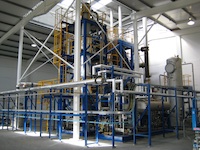
There was a positive message, also, about Carr's engineering division, which reported increasing global demand for remote handling equipment and robotics from the nuclear and petrochemical industries.
Its Wälischmiller unit, based in Markdorf in southern Germany, found buoyant demand for remote handling and robotics products.
"Several major contracts have been completed in the period and the order book continues to be healthy," said Carr's, noting plans for additional capacity.
Meanwhile, Bendalls' multi-million dollar contract with Hyundai to supply pressure vessels for BP Quad 204, west of the Shetland Islands, will be near-complete by the end of the financial year, with the remainder delivered by December.
Sales momentum at Carrs MSM accelerated during the period with the business benefiting from the ‘life of plant' contract at Sellafield, and financial performance is ahead of budget, the group concluded.
(Image source: Carrs)
 A project to establish a new waste processing facility, including a plant to turn waste plastics into diesel is still progressing at Avonmouth, near Bristol, according to Sita.
The Bristol Resource Recovery has recently seen the installation of an 80-kilotonnes-per-annum materials recycling facility that can handle dry mixed recyclables, said a Sita spokesman in a written statement to PIM.
"Adjacent to the MRF, we are currently close to completing the end of life plastics-to-diesel facility," he added. "This facility will handle some of the harder to recycle plastics, such as margarine tubs, yoghurt pots and plastic films. I expect to provide a formal press update a little later this year."
Plastics-to diesel technology company Cynar previously stated that the Avonmouth facility would start-up in late 2012. According to the Sita spokesman, though, there was no strict deadline set for the plant to become operational.
"We have just steadily progressed with both the MRF and the plastics to fuel plant," he said. "We did have to stop work on the Bristol Resource Recovery Park for a few months though in 2012 as we encountered some potential issues with the ground.
"However, we were given the all clear shortly after the attached story appeared in the local media and work recommenced."
Cynar's collaboration with Sita envisages the establishment of several sites using its process technology across the UK.
Rockwell Automation is also partnering Cynar, which already has a plant up and running in Portlaoise in the Republic of ireland.

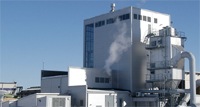
German bioethanol producer CropEnergies AG is to invest more than £50 million to improve the competitiveness of the Ensus bioethanol site, which it has just acquired.
The facility at the Wilton International site on Teesside in the northeast of England is one of the largest bioethanol production plants in Europe. It is scheduled to restart under its new ownership after essential maintenance work is completed.
Under a deal completed 19 July, Ensus' former equity-fund owner Carlyle Group will become a minor shareholder in CropEnergies, which is based in Mannheim, Germany.
Ensus started up its bioethanol plant early in 2010, employing around 100 people. However, the operation has since been halted a number of times due to commercial and regulatory issues affecting the biofuels market.
The Teesside plant has an annual capacity of 400,000 cubic metres of bioethanol and 350,000 tonnes of dried protein animal feed. In addition, carbon dioxide is delivered to an adjacent liquefaction plant which processes it for use in the food and drinks industry.
Ensus will become a key part of CropEnergies existing biofuels production network and operate on a much stronger footing, according to Peter Sopp, chief executive officer of Ensus.
"As one of the most successful bioethanol producers in the industry, CropEnergies bring huge expertise and experience in this field, as well as a strong commitment to invest further in the Ensus operations in the UK” he said.
The acquisition increases CropEnergies' bioethanol production capacity of bioethanol by 50% to more than 1.2 million cubic metres a year.
The German company also gains access to the UK bioethanol market – the EU's third largest market for bioethanol after Germany and France.
The company already operates production plants for bioethanol in Germany, Belgium and France and is also investing Euro27 million to build a processing plant for neutral alcohol in Zeitz, Germany.
(image source: Crop Energies)
 Helius Energy plc has handed over the biomass energy plant in Rothes, Speyside, Scotland to Helius CoRDe Ltd (CoRDe) – a joint venture between Helius Energy Plc, Rabo Project Equity BV and the Combination of Rothes Distillers Ltd (CoRD).
The transfer follows the completion of trials at the plant which uses by-products from nearby malt whisky distilleries to produce renewable energy and liquid animal feed product (pot ale syrup). The unit will be accredited as a CHP plant under Renewables Obligation legislation.
The project, which includes an 8.32MWe power plant and a 66.5t/h pot ale evaporator plant, is owned and operated by the CoRDe venture. It will will save around 46,000 tonnes per year of CO2 compared to a similarly sized coal-fired facility.
A further reduction of 18,000 tonnes of CO2 per year will be achieved by closing the existing gas-fired CoRD facility located at the same site.
During performance trials the plant achieved gross power output of 8.4MWe and achieved the net design throughput of 73.2t/h of pot ale through the evaporator plant, Helius reported.
The project will generate revenues from index-linked gate fees received for the processing of distillery residues, the sale of electricity and associated ROC sales, and the sale of Spey Syrup into the animal feed market.
According to Helius, CoRDe will continue actively to explore opportunities to increase the distillery residues processed by the project.
Helius is also developing a 100MWe project at Avonmouth and bringing forward a similar scale scheme in Southampton, the company said 15 July.
(Image source: Helius Energy)

Mitsubishi Electric has launched its next generation of servo systems, comprising the Melservo MR-J4 series of servo amplifiers with associated positioning units, motion modules and integrated motion control systems.
The series represents a significant advance in servo system technology and provides benefits to machine builders and end users, according to the company. Target 'process' applications, it says, include high-accuracy filling and dosing applications in the food and pharmaceuticals industries.
The update on the J3 series, launched back in 2004, incorporates a range of functions that are intended to boost performance while minimising the time-consuming effort of engineering and setting up servo systems.
The MR-J4 series features single-, dual- and triple-axis amplifiers for improved economy, greater energy efficiency and reduced panel space requirements. The servos can all operate with rotary, linear and direct drive motors, and so simplify the system-building process.
According to Mitsubishi, engineering and commissioning time is drastically reduced thanks to the “one touch” auto tune function, which matches the machine mechanics to the servo system in a single operation. This function operates in real time and is dynamic, so if the machine conditions change over time, the MR-J4 system tuning automatically adjusts.
Covering the range from 0.1kW to 55kW, MR-J4 servo amplifiers are available in two versions. The MR-J4A provides analogue and pulse train connections and is designed for conventional control systems and for speed, torque and closed-loop position control.
The MR-J4B comes with connectivity to Mitsubishi’s SSCNETIII/H high performance servo network, meeting the needs of integrated automation systems where complex multi-axis motion control is required. S
SCNETIII/H control information is delivered over a duplex 150Mbps fibre optic bus, which is said to simplify connection and commissioning and permit synchronous coordination of up to 96 axes. Both versions of the amplifier come with built in local I/O for interfacing with signals such as over travel limits and print mark registration.
The MR-J4 amplifiers also include a “life diagnosis function” which monitors the condition of the amplifier at a component level and notifies the user of any degradation in its operation. This feature also has the ability to recognise changes in machine dynamics such as increased vibration and increased motor torque.
The servo motors are fitted with 22-bit absolute encoders as standard, corresponding to more than four million pulses per revolution. This, claims Mitsubishi, outperforms the accuracy of other servo motors on the market by four times and so provides "excellent true-running characteristics and maximum positioning accuracy."
A Mitsubishi release further claims: "Combined with the processing speed of the MR-J4 servo amplifiers and their 2.5kHz frequency response plus inbuilt vibration suppression filter, the result is vastly improved machine performance, with minimised positioning times, reduced cycle times and greater throughput."

A patented fine grinding technology is being used as part of a new research project designed to extract and recycle metals from portable battery waste.
The ReCharge project is being funded by the Technology Strategy Board and managed by technology innovation centre the Centre for Process Innovation (CPI) to develop an economically viable means of extracting and reusing valuable metal concentrates from discarded batteries.
As part of the scheme, a fine grinding technology developed by International Innovative Technologies Ltd. (IIT) is being used to reduce the ‘black mass’ solid inner core of alkaline batteries into a powder form.
After reducing the black mass to a powder, the material is then suitable for treatment by different chemical and biological processes to extract the various metallic ions present, including zinc, carbon and manganese.
Engineering advances made by IIT have enabled the development of specialist powder processing technology that replaces traditional milling systems with compact, high output, modular units. The new vertical milling system is highly energy efficient and is therefore particularly suited to the fine grinding of hard and abrasive materials.
Under CPI’s project management, the consortium of companies involved in the ReCharge research programme also includes G&P Batteries and Augean plc.
With the UK Battery Waste Regulations now in force, the volume of battery waste required to be recycled is increasing. The UK has no processing facilities for portable battery waste, with all collected batteries currently being exported for recycling purposes.
Moreover, despite the growing number of retail and household recycling collection points, several thousand tonnes of harmful battery waste are still going into landfill.
To overcome this situation, CPI is working with the project partners to design a process to successfully recycle the metals from batteries for re-supply into a range of manufacturing applications.
When developed the intention is that the technique can also be applied to other high metal concentrated waste streams.
The IIT m-series technology is already utilised in a number of glass and GRP recycling applications.
The process is also suitable for the low-energy milling of materials, including aluminium oxide, silicon carbide, zirconium, limestone products‚ coal, fly ash and furnace slag.

Engineers must understand the implications of modifying explosion-proof (Ex d) enclosures as part of the certified equipment prior to and after installation, says Toni Ott, Manager rest, certification and patents at Cooper Crouse-Hinds GmbH:
Whether sourcing Ex d flameproof equipment for offshore oil platforms or onshore petrochemicals plants, it is critical that end users and installers fully understand the implications of modifying these enclosures. It is important that end users fully appreciate what they are allowed to do with that Ex d enclosure so as not to invalidate the certification of the complete equipment.
The primary function of an Ex d enclosure is to prevent the propagation of an internal explosion to the surrounding explosive atmosphere, and protecting the internal components from the environment, humidity, dirt, dust or water. With Ex d flameproof enclosures, it is critical that the flamepath is not damaged. The external enclosure of any flameproof electrical equipment is designed to withstand an internal explosion.
The enclosure joints therefore permit and control the resulting expansion of flames and hot gases – as these are relieved through the joints, preventing that explosion transmitting through to the external atmosphere. The relevant European (EN 60079-1) and International standards (IEC 60079-1) in addition to EN/IEC 60079-0 “General Requirements” apply.
In Europe, manufacturers and end users have to consult two Directives: 94/9/EC covers equipment and protective systems intended for use in potentially explosive atmospheres (ATEX) and is for the manufacturers of the equipment.
For end users, Directive 1999/92/EC “Risks from Explosive Atmospheres” (December 1999) outlines and harmonises the minimum requirements for improving the safety and health protection of workers potentially at risk from explosive atmospheres.
There is no Directive covering the middle ground i.e. modifying an existing Ex d enclosure by neither a manufacturer nor within the full responsibility of the employer (end user). Once Ex d equipment has left the manufacturer and its quality system (requirement to affix the CE mark on the type label), it is no longer the responsibility of the manufacturer but lies with the end user.
Common pitfalls
Increasing awareness of relevant standards and education are fundamental. Mistakes occur due to a variety of reasons, for example, lack of knowledge or inexperience.
One of the most common mistakes made by end users and installers is to drill new cable gland entries into an Ex d enclosure after or prior to installation. If space allows, an end user may decide to fit additional components into the enclosure such as a switch or an additional component with relevant power loss.
This type of modification can affect the temperature class rating of the equipment’s enclosure or could lead to the overheating of other components inside the box, which in turn, may result in component failure or give rise to an ignition source. In addition, these modifications could also weaken the mechanical integrity of the enclosure or lead to altered flame propagation within the enclosure, resulting in excess of the maximum permitted reference pressures.
Also, the results of the flame transmission test performed during the EC-type examination procedure could be negatively affected and a possible internal ignition will not be safely controlled by the existing flameproof enclosure from the external explosive atmosphere.
Therefore, according to Directive 94/9/EC, only the manufacturer shall carry out such modifications. If the modification is carried out by another party, without control of the quality management of the original manufacturer, the marking on the equipment is no longer valid.
Therefore, if any modifications are made to an Ex d enclosure and these are not within the responsibility and agreement of the equipment manufacturer, only two options exist:
-
New EC-type examination certificate with new type label is the responsibility of the legal entity modifying the equipment, or
-
The end user takes full responsibility which means they also become responsible for any subsequent failures of the enclosure that could lead to serious health and safety risks.
Other examples of modifying an Ex d enclosure include accidentally damaging the flameproof gap. When opening heavy enclosures, which typically involves unscrewing fasteners and lifting the cover, maintenance technicians must be careful not to inadvertently scratch or damage the flanges or threads. The cover should be lifted slowly and smoothly off the enclosure.
Painting an Ex d enclosure, particularly if paint gets in and around the flame gap, can adversely affect the certification. Also, screws that are painted over can prevent access to the box. As paint is typically non-conductive, this can also lead to electrostatic hazards and introducing a new ignition source.
Another common mistake when placing the cover back on an Ex d enclosure is to fasten the screws to the wrong torque or to forget to replace screws. This is particularly important on Ex d gas group IIC enclosures (including IIB + H2), where the tolerance of the flameproof gap is typically down to 0.1mm.
It is critical that all screws are tightened to the correct torque as specified by the manufacturer. If this isn’t done, the cover can bend and lead to an uneven flame gap. Of course, the same problem remains for IIB and IIA enclosures.
With flame gaps, the impact of grease is also important. Often, there are misunderstandings amongst end users and installers about which greases should be used with an Ex d enclosure. In general, the grease that should be used is the one recommended by the manufacturer.
The message is clear for all cases – if you are in doubt, consult the enclosure manufacturer for advice and guidance on grease selection. The grease recommended by the manufacturer will have been tested at the applicable ambient temperature range. Incorrectly selected grease may harden at low temperatures or may turn into an adhesive at higher ambient temperatures.
As for relevant standards to consult, EN/IEC 60079-19 provides end users with technical instructions on the repair, overhaul and modification of equipment designed for use in explosive atmospheres. For design, selection and erection of electrical installations in explosive atmospheres, EN/IEC 60079-14 is the relevant standard to be used.
After an Ex d enclosure has been installed correctly, EN/IEC 60079-17 outlines the principles that the operator should adhere to in terms of maintenance (inspection, service and repair) of the equipment, including advice on the issue of safe work permits.
Certification Tests
Buyers of Ex d enclosures should also be aware of the certification tests involved. The tests to be performed are defined in EN/IEC 60079-0 (general requirements) and in EN/IEC 60079-1 for the type of protection “flame proof enclosure”, known as “Ex d”.
For all Ex d equipment, thermal tests are conducted to determine the maximum surface temperature of the complete equipment (enclosure and inbuilt parts) under maximum service conditions with a safety margin added.
Additional thermal endurance of heat and cold (non-metallic enclosures or parts of enclosures) are tested and impact tests are always carried out on critical parts. The tests above or definitions made to prevent an electrostatic ignition source from becoming effective, are also performed.
For Ex d enclosures (EN/IEC 60079-1) additional tests that are normally carried out involve Reference Pressure, Overpressure and Flame Transmission. Additional tests are necessary, for example, for light transmitting parts made from glass or breather plugs.
The Reference Pressure tests involve filling the enclosure with an explosive mixture of gas and igniting it. The reference pressure depends on the lower ambient temperature (the lower the temperature, the higher the reference pressure) of the enclosure and of the geometry to be found within the enclosure. Following these tests, a hydrostatic overpressure test is conducted to verify the mechanical strength of the enclosure.
Following overpressure tests, the enclosure is also subjected to a series of flame transmission tests, using a similar explosive mixture of gases as before. The enclosure is also placed in an explosive atmosphere.
When the internal explosive mixture is ignited, it is not permitted for this to transmit through the flameproof joints to the outer external atmosphere. Flame propagation depends on the upper ambient temperature of the enclosure/equipment and on the internal geometry.
When exceeding the given ambient temperature range stated by the manufacturer, the equipment will typically no longer be safe. The same is true for the mechanical integrity of the enclosure when exceeding the lower ambient temperature. Modifying the internal dimensions, especially when reducing the cross-sectional area, will have a similar result.
For enclosures that have an ambient temperature range higher or lower than -20 deg C to +40 deg C, the reference pressure overpressure and flame transmission tests may be conducted at the extremes of low and high ambient specified by the manufacturer.
Sometimes, complete Ex d assemblies are put onto the market with only a “U” at the end of the certificate number. This is not permitted because this shows that only the empty enclosure has been certified, not the complete assembly. Typically, the temperature class is not shown on the type label because the heat loss of inbuilt components is not known by the manufacturer of an empty Ex d enclosure.
Customers are increasingly looking for suppliers that can help them meet global compliance requirements whilst at the same time increasing productivity levels.
There are many different safety bodies out there, all running competent safety accreditation schemes and it can be a bit of a mystery to know what best fits with an application's requirement.
For machinery solutions you can take an exam and become functional safety specialist through a number of different test houses, but in my opinion TÜV Rheinland has the most exacting requirements; with its 'expert' level demanding at least 10 years’ experience in a safety role.
Customers are not just interested in solutions and products, they want good advice too. However, products, solutions and advice all need to work in harmony to help ensure peace of mind for machinery/equipment suppliers and manufacturers.
How do they know our products offer the right performance? They are TÜV certified. How do they know that our personnel can design and specify the right solution? Once again they are TÜV certified.
Safety maybe a moving target, but the right supplier can bring the target a lot closer giving you a much better chance of hitting it in the centre.

Dr Jim Marshall, policy and business adviser, Water UK – Edited speech 'Understanding the impacts of shale gas on the UK water industry” at – UK Shale 2013, 17 July 2013:
Provision of drinking water is a cornerstone of our public health and as such a service that cannot be compromised. The subject of water needs to be addressed and planned - not taken for granted or as an after thought.
The physical or chemical quality of the water we drink is just one aspect. Equally important is the perception of water. Of people's trust in it if you will. Without that, it doesn't get drunk and it makes no difference that we have the best quality water in the world - and arguably we do.
So if people lose confidence then we also have a problem -- and I mean we all have a problem. You from the perspective of your social contract to operate but also the water company has a problem with our reputation.
Water is being used by opponents and proponents of fracking in equal measure but we aren't taking sides. What I want is for water to be considered at the right time in an open manner.
Sure there are challenges and we need to be upfront about those. Now is the time to address them and get the frameworks in place. If we do that then water won't be an issue. If we get it wrong then water has the potential to stop the industry in its tracks.
It is difficult to draw direct comparisons with other countries or sectors. Water is essentially a local factor and requires a local plan to effectively manage it.
But it is important to look across and see what others have done - for example some of the work done by Halliburton and others on recycling of flow back or adapting technology from areas such as southern Europe or Israel where they have to work more with saline waters.
But we need to deal with our challenges in their own right.
Last year the water industry commissioned its own research into understanding the potential impacts. This is due to be published soon and some of my thoughts are related to this report.
Broadly speaking there are four - water quality, water quantity, removing and treating waste water and infrastructure.
Drinking water in the UK is the best in the world -- not my statement but that of the OECD.
Since the English and Welsh industry was privatised we have spent over £20 billion upgrading works, investing in new tech and improving the pipes bringing it to our houses. We are proud of this record and the UK should not jeopardise its position.
Ways of working have shifted focus slightly in recent years. We don't simply rely on treatment to remove all contaminants prior to drinking. It's better, more sustainable, to deal with problems at source.
Take pesticides or pharmaceuticals -- these compounds are becoming increasingly common in river waters. The trouble is its very expensive to take them out during treatment. Therefore we try to focus on addressing the problem at source. Water companies have to carry out risk assessments on all their drinking water supplies.
These are known as safety plans and require the assessment of risk at every stage of the process from the source to the tap. If something happens anywhere along this route then companies need to consider it and ensure that there are barriers in place to protect water at its end point – the point of supply to kitchen tap.
There are risks to water quality associated with any activity taking place in a catchment.
Shale gas wells are another risk we have to assess, understand and plan for. To do this we need you to help us understand the risks - to get the truth from the noise.
What are the risks and can they be quantified for example:
• contamination of aquifer as a result of fracturing running through geology;
• contamination via a failure in the well casing;
• direct contamination of surface waters from poorly managed waste water or chemical handling?
• tertiary risk associated with traffic movement or drilling in general.
Shale gas reserves and drought
This isn't particularly unusual. Only last week there were stories in the press about water shortages meaning that food supplies will become more reliant on imports begging the question where do food policy and energy policy meet? With water?
Water in this country isn't particularly well connected. We don't have a national water grid or a system of canals to shunt water from north to south. Water companies have some options to balance supplies but in the grand scheme of things these are still relatively local.
The only way to bring water into an area is to either abstract it from local sources, take advantage of tap water, recycle returned fluids or rainwater or tanker it in.
You could have a direct abstraction from a river or groundwater source. This would need to be licensed by the EA (or Natural Resources Wales) who would look to CAMS to assess the water availability locally, what the other demands are in that area and if water can be used more efficiently.
Our research analysed the resource situation in the main shale gas areas and concluded that – with the exception of Northern Ireland and the Bowland Basis – the situation is variable and depends on the location of the specific well fields. The Weald basis for example is currently over-abstracted.
You may want to consider a supply of potable water from the local water company piped directly to the fracking site. From discussions I have had treated drinking water is your ideal. It's clean, it’s available reliably and it’s got a built-in biocide. If you were to take potable water you would need to consider the size of the infrastructure needed to meet the demand.
You could get your water provided by a tankered water supplier – such as Water Direct. This could allow water stress issues to be overcome but what about the visual impacts of truck movements -- a challenge I know is one that you already face and is a very public issue.
Or you could invest in some form of water recycling or reuse. From the figures I have seen there should be a sizeable percentage of water recovered from the ground after fracking.
The trick will be to look at recycling options to reuse this water – perhaps coupled with rainwater collected from the site - to reduce the burden on fresh water supplies.
Getting this water back to the optimal chemistry to allow effective use of the fracking fluid will take some treatment on site. But I understand it is possible. In Manchester recently we heard from Halliburton about how they have formulated frac fluids to deal with the demands of recycling flowback water for reuse. There is work to be done but its an option.
The reality may be a combination of these approaches. With a connection to the mains augmented with recycled water, on site storage and tankers to meet the peak demands. The configuration would vary locally and perhaps even seasonally.
What would be useful would be for operators to produce a water management plan for each site or play. We do similar things with farmers and have found that by really considering water it can be used more efficiently. This has a benefit to the environment – less water out – but equally importantly I'd argue it’s a benefit to your bottom line -- water costs money.
Waste water
The next challenge is what to do with the water that is no longer needed. Taking aside the discussion on reuse the chances are that there will be volumes of water that need to be removed from the site. The research carried out on behalf of the water industry has indicated that flowback water should be treatable at larger urban waste water treatment facilities.
Flowback waters are typically highly saline – which is toxic to bacteria used in the treatment process - so it will only be these larger works that can provide the required dilution.
That said, more consideration needs to be given to: water containing naturally radioactive materials or NORM; transportation of waste to works; and how costs can be fully recovered so that water customers don't end up carrying the can.
None of these challenges will be new to you and indeed you may have other challenges from your perspective that I haven't really covered. In simple forms reducing your water impact will save money. Getting water right is also essential as part of your social contact.
It’s also true that none of them are insurmountable - by regulation and enforcement, by innovation and most importantly through communication and collaboration.
We have heard already from the EA that the environmental regulations are in place. What we need to add to that is the roles of Ofwat and DWI in regulating the economic and drinking water aspects of the water industry.
Having spent some time looking closely at the regulations I honestly believe that they are robust. I think there could be a tightening up of some of the European legislation around impact assessments. The Commission however are developing a framework for shale gas that they assure me will capture everything - we wait.
Perhaps of more importance is the ability of the regulators to audit, inspect and enforce.
The EA has been cut in recent years and has a fraction of the resource it used to have. It is not uncommon for the regulated to pay the costs of regulation and I suspect a similar model may work for shale gas.
But that's up to [industry] and the EA to discuss. What is important is that to maintain the credibility of the sector that proper robust audit and enforcement is carried out.
A quirk of the planning process is that water companies are not statutory consultees. We rely on the EA to flag up water related issues. We think this is inefficient and are lobbying to correct this. However that will take time to change.
In the meantime, setting up direct communication links between operator and water company is essential. It works in the north west with Cuadrilla and United Utilities in regular contact - although I understand that initial approaches could have been made earlier.
I have spoken to a lot of water companies about [these issues] in recent months and they are generally as unsighted about the impacts of shale gas as other members of society.
Some, in anticipation, are starting to do baseline quality monitoring. Others are looking at their water resource management plans to see what impacts it could have. Others are just simply waiting to see what comes about.
There is a bit of a theme here - talk and talk early. The earlier the engagement with the water company, the better the decisions that can be made.
Maybe a site could be provided with water more easily if it was planned a mile to the west or maybe there could be options around on-site storage or access to raw water. Maybe some of our supply chain could help bring innovation and different ways of thinking to the party.
What is needed at this stage is a clarification from both sides. I am hearing the need for a “cards on the table” session with water companies and shale gas operators. Let’s get the key people together.
We can discuss each other’s perspectives – see where the real barriers are and where the opportunities exist. This should happen sooner rather than later. I propose that Water UK are in a position to be able to bring something like this together inwhatever format works best.
I can visualise an output of a ways or working or MoU or just a better understanding of the impacts of shale gas on the water industry. It feels like this should happen this summer or at the vary latest early autumn. What do you think?
Provision of drinking water is a cornerstone of our public health and as such a service that cannot be compromised. Public health is as much about perception and trust as it is about absolute quality. Water needs to be properly addressed and planned for - not taken for granted or as an after thought.
 Total has installed a new 11 kV substation at the Lindsey Oil Refinery (LOR) as part of an ongoing upgrade of the power distribution infrastructure at the North Lincolnshire site.
Located five miles from the Humber River estuary, LOR is currently the UK’s third largest oil refinery, processing 10 millions tonnes of crude per year.
The refinery's processes require an extensive power network comprising several substations from 11 kV down to the sub-distribution level of 415 V.
The site is currently carrying out a replacement programme to bring its 11 kV and 3.3 kV switchgear assets up to the latest performance, reliability and safety standards.
One element in the upgrade programme was the recent replacement of the strategic 1A/2B 11 kV substation that acts as a main power distribution hub for the site. The work had to be completed within the tightly defined 32-week window offered by a planned turnaround and inspection outage.
The timescale and space constraints at the selected location - right in the heart of the refinery - made it difficult to build a new substation building, especially in carrying out the substantial civil works to meet blast=rating requirements.
ABB, therefore, suggested a containerised substation in a blast-rated enclosure, delivered ready to ‘plug and play’ and installed on deep piled foundations to withstand blast shockwaves.
The containerised substation comprises 26 panels of ABB’s UniGear ZS1 MV switchgear. The design of this 50 kA fault rated switchgear, including front cable access, enabled it to be configured as two front facing rows – 1 x 14 panel board and 1 x 12 panel board – joined via a low-level bus-trunking link.
The design of the UniGear panels meant that they could be positioned 100 mm away from the internal wall. Yet the design still enabled the thick blast-proof container walls, two rows of panels and a central walkway to be accommodated within the maximum 6 metre width allowed for standard containers to be transported on the UK roads.
The ability to fit the entire packaged substation within the footprint of a single container was crucial in ensuring the ease of handling and installation of the substation solution, noted ABB.
If two containers had been required then not only would the installation have been more complex, there would have been considerable challenges in ensuring the blast-proof integrity of the completed substation, the supplier said.
A further factor in the compact design was the use of ABB’s REA arc-flash protection system that eliminated the need for a conventional, and space consuming, high impedance bus-zone protection scheme.
The REA system uses fibre optic light sensing and fast switching techniques to continuously monitor areas of the switchboard and, if the light from a developing arc fault is detected, it will trip the incoming breaker in less than 2.5 ms. This removes the incidental energy in as short a time as possible, preventing damage and/or safety issues.
The LOR substation project also involved the use of ABB’s Relion IEDs (intelligent electronic devices) to provide a relay solution for functional requirements including generator protection, feeder protection, transformer protection and line differential protection. Initially the IEDs are operating on the Modbus protocol.
Although they can operate via fibre optic links in new build substations, the IED units are also suitable for retrofit installations where they can utilise existing copper pilot cables via a modem link.
ABB also supplied its RTU560 remote terminal unit to meet LOR’s local HMI requirements by enabling the new substation to be integrated within the previously localised 11 kV site network, and to access equipment remotely which had not previously been possible.
The switchgear, REA arc flash protection system, IEDs and RTUs are housed in the single factory-fitted container complete with back-up batteries.
Following on from substation 1A/2B, ABB is now working on substation 16 that will provide a new power intake connection from Northern Powergrid for the LOR site, as well as the connection for the main 40 MW back-up generator.
This has essentially the same scope in terms of design, delivery, installation and commission of the complete substation solution, but due to its non-critical location will be installed in a conventional substation building.
Substation 16 will feature 3150 A busbars, and an uprated version of the UniGear ZS1, rated at up to 4000 A and 50 kA fault current will be installed. The switchgear is a withdrawable pattern design that features ABB’s VD4 vacuum circuit breakers.
According to ABB, its Relion IEDs will be fitted that will enable Substation 16 to utilise the full inbuilt capability of the latest IEC 61850 communications standard for substations.
(Image source: ABB)
More...
![]()
A £1.2-million investment is to be made between Green Investment Bank (GIB) and Equitix in partnership with Balcas to install a steam generating biomass boiler at Tomatin Distillery near Inverness.
The Equitix managed fund, Energy Saving Investments (ESI), in which the GIB is a cornerstone investor, is providing £576,733 to finance the installation of a biomass boiler at Tomatin Distillery near Inverness.
This £1.2 million investment, GIB's first in Scotland, mobilises a further £600,274 of investment from the Equitix Energy Efficiency Fund (EEEF).
The investment is being made by ESI in partnership with Balcas Litd, a UK manufacturer of wood pellet biomass.
GIB awarded the competitive fund mandate to Equitix to invest £50 million, matched by private investors, to drive investment in small-scale low carbon infrastructure requiring less than £30 million of financing.
Equitix has also established EEEF to make investments into the energy efficiency sector, including as co-investors alongside ESI.
The boiler installation at Tomatin Distillery, 16 miles south of Inverness, produces steam used in the production of whisky. The boiler, manufactured by a major European manufacturer, replaces an oil-fired boiler.
The new boiler will replace 80% of the heat load usually generated by the oil fired boiler. It will be fuelled by 'sustainably sourced' wood pellet fuel and could cut CO2 emissions by over 96,500 tonnes over the 20-year life of the investment.
It will use 'EN plus A1' standard pellets, manufactured by Balcas using renewable electrical and thermal energy and raw materials sourced from local, sustainably managed forests by Balcas at their plant at Invergordon.

Aker Solutions has won a contract worth up to $440 million to deliver the subsea production system for an oil field development in the UK North Sea. The company did not name of the field or the operator.
The deal, which is Aker's single-largest subsea contract in the UK, includes the delivery of 25 subsea trees and six template manifolds. It also encompasses associated controls, wellheads and tie-in equipment for one of the biggest projects currently under development in the UK North Sea.
According to Aker, the order includes subsea technologies that are new to the UK market, including manifolds and trees that can enable the use of hydraulically submersible pumps to improve oil recovery and flow assurance.
The Norwegian company will also provide diverless horizontal tie-in systems and slim line rigid lockdown wellheads for the development.
First deliveries are scheduled for the first half of 2014. Aker's main office at Fornebu in Norway will handle central management, engineering and procurement for the project.
Its Tranby facility outside of Oslo will manufacture the subsea trees, while production of the manifolds and system integration testing will be carried out at the company's offshore yard in Egersund on the west coast of Norway.
The company's subsea operations in Aberdeen will manufacture the control systems and wellheads and provide lifecycle-support services.
![]()
AkzoNobel’s UK decorative paints business has gained the Carbon Trust Water Standard, becoming one of only six companies in the world to receive the certification since its launch in February – joining major names such as Coca-Cola Enterprises and Sainsbury’s.
The award recognises reductions achieved through a huge programme undertaken to cut water usage at AkzoNobel. Measures have included the introduction of rainwater harvesting to feed manufacturing processes and a programme to reduce water leakage across plants.
AkzoNobel has also streamlined production processes reducing the number of cleaning cycles needed and increased storage capacity for wastewater at manufacturing sites. The latter step has meant that more wastewater can be incorporated into product formulations, cutting the need for fresh water.
AkzoNobel is the largest global paint and coatings company. The UK is a key location for the manufacture and retail of its decorative paints, including iconic brands such as Dulux, Dulux Trade, Polycell and Cuprinol.
The company has been ranked in the top three in the influential Dow Jones Sustainability Index since 2007 and was ranked first in the chemicals supersector last year. It also holds certification for carbon reduction from the Carbon Trust.
AkzoNobel's 1,100-employee UK decorative paints business will soon be expanded by the opening of a new site in Ashington in 2014. This plant will exemplify the business’s commitment to sustainability with ambitious plans including ensuring all water is re-used.
“Radical resource efficiency, doing more with less, is central to our sustainability strategy and water reduction is an important part of responsible resource management," said Chris Cook, AkzoNobel’s global sustainability director for decorative paints.
"We have driven down water usage at our plants and we are determined our new plant in Ashington will be the most sustainable paint plant ever with state-of-the-art processes driving down energy consumption and waste.”

Premier Foods is to reorganise its milling business into two parts to strengthen its focus on its third-party customer base, while vertically integrating its remaining milling operations into its baking and grocery businesses.
The company is also planning to close its mill located in Barry, Vale of Glamorgan, by the end of October 2013. The move, it said, would help to align capacity with current market demands.
A new dedicated management structure is to be established to oversee the Rank Hovis third-party business. This will be largely serviced by the company’s sites in Southampton, Manchester and Newbridge.
The remaining mills in Wellingborough, Selby, Andover and Gainsborough will be organised into a vertically integrated flour supply business for the company’s baking and grocery business, said Premier Foods.
Around £1million has been earmarked to improve the capability of the Southampton and Wellingborough sites as part of this re-organisation.
The Barry closure is to be phased over the coming months with final closure expected by the end of October 2013, resulting in the loss of around 43 employees plus a smaller number of local contractors.
“By creating a dedicated structure aligned to our Rank Hovis customers, we will be able to improve further our customer focus and service levels,” said Bob Spooner, managing director of Premier Foods’ bread division and group supply chain director.
“It’s also critical that we take the tough decisions necessary to improve the longer term profitability and sustainability of the milling business by aligning our capacity to market needs.”
“We recognise the impact this proposal will have for our employees in Barry and we thank them for their contribution over the years. However, it’s not possible to continue on the current path given excess capacity in the marketplace.”