Displaying items by tag: Microplastics
Microplastics in biological wastewater treatment and how to avoid them
The term “microplastic” has been used for the first time approx. 10 years ago and refers to small plastic particles with a diameter of less than 5 mm. A differentiation is made between microplastic particles which are being produced for practical usage (e.g. in cosmetics) and microplastics that are originating from the degradation of larger plastic products (plastic waste).
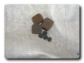 Fig. 1 Foam-type carrier: virgin material (left) and abraded material (right)Needless to say, microplastics do not stop when it comes to water and wastewater treatment plants and the pollution of the aquatic environment and water cycles in aquaculture is increasingly being discussed.
What is the reason for that?
In the water and wastewater treatment the moving bed biofilm reactor technology (MBBR) has been very successfully used for decades and has become almost indispensable (depending on the field of application). Various types of carrier media are being used for the immobilization of microorganisms within this MBBR reactors.
Now, it is found and under due consideration that the application of those plastic elements (biofilm carriers) lead to a pollution of the waterbody by microplastics whereas in fact, the intended purpose of those plants is water purification. What is the reason for that? Can this risk be avoided in order to maintain this important technology?
In MBBR systems, plastic carriers have always been used. Due to their geometry or material characteristics, they may release microplastics through abrasion or wear, respectively.
A particularly high level of wear has been repeatedly found with soft foam cubes made of PU (polyurethane) which had to be replaced with new material due to suchlike signs of wear.
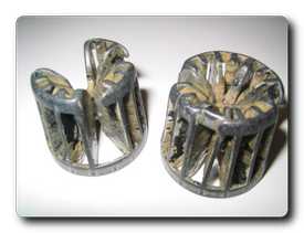 Fig. 2 Carriers damaged by too high kinetic energy The wear is caused by abrasion (Fig. 1), by contact/collision with each other (Fig. 2) or by collision with tank walls or tank-internal installations. Besides the material characteristics of the carrier, the kinetic energy plays a major role. The kinetic energy indicates the energy with which a moving body collides with another body or tank wall. The basic formula is Ekin = (1/2) m V 2. Therefore, the crucial factors are the mass of a single carrier element and its kinetic energy. In order to allow for smallest possible kinetics, a carrier should be “as light as a feather” and should be moving at low velocity within the water. The ideal case would be a free-floating carrier without movement in the water which is however only possible from a theoretical point of view. Yet, by the water flow itself and by aeration, if any, the carrier media is being moved.
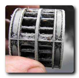 Fig. 3 Carrier with signs of abrasionOne affecting factor is the “mass” of the body which is, amongst others, influenced by its geometry. For example, it has been found with hollow bodies (tube-shaped; helical carrier) that inactive biofilms from dead biomass can be formed within the internal space which affects the mass of the body. As a consequence, this mass cannot participate in the further exchange of substances and the metabolism. The dead biomass in the internal space of the hollow body is thus unnecessarily increasing the mass or weight of the latter, respectively, resulting in an increased level of wear. The thereby occurring abrasion can be added to the term of microplastics.
The figures mentioned-above and below show various carrier elements at certain levels of wear due to abrasion.
MBBR carrier media for an environment-friendly future
Contrary to the various hollow bodies or foam cubes, a thin, chip-type carrier shows no abrasion. This fact has been proven in numerous reference plants with more than 10 years of operation. The reasons are complex but logically comprehensible. At first, a chip-type carrier has a very low tare weight due to its solid HDPE foam structure. Its outer protective ring acts like an elastic buffer or crumple zone. Due to the thickness of approx. 1.1 mm, active biomass can establish on both sides and is supplied with substrate and oxygen due to the optimal diffusion depth. The chip is not loaded with dead biomass and thus the kinetic energy is very low.
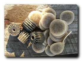 Fig. 4 For comparison: clogged carrier (left) & chip-type carrier (right)Due to its geometry and movement characteristics, the chip is moving at a very low velocity which essentially uses the low kinetic energy to its further advantage through the calculation v2 (squaring of the velocity). Heavy, large bodies move at a higher velocity.
The chip is being “lubricated” all around its surface by the biofilm which provides sufficient protection for the carrier body. As known from lubricated slide bearings, the lubrication film does not cause any abrasion.
Hence, such-like carriers cannot cause environmental pollution in the form of microplastics and they continue to contribute to environmental protection by their high efficiency.
© Multi Umwelttechnologie AG, 2019
Authors:
Christian Börner
Cornelia Harmsen
This email address is being protected from spambots. You need JavaScript enabled to view it. | www.mutag.de |